SIMULATION -
Instructions -
To configure a switch click on the console host icon in the topology.
You can click on the buttons below to view the different windows.
Each of the windows can be minimized by clicking on the [-]. You can also reposition a window by dragging it by the title bar.
Most commands that use the "Control" or "Escape" keys are not supported and are not necessary to complete this simulation. The help command does not display all commands of the help system.
Scenario:
You work for SWITCH.com. They have just added a new switch (SwitchB) to the existing network as shown in the topology diagram. You have been tasked with completing the needed configuring of SwitchA and SwitchB.
RouterA is currently configured correctly and is providing the routing function for devices on SwitchA and SwitchB. SwitchA is currently configured correctly, but will need to be modified to support the addition of SwitchB. SwitchB has a minimal configuration. SwitchA and SwitchB use Cisco as the enable password.
All interface commands must be entered at the physical interface level.
When entering the range command, add a space between the interface numbers (e.g., fa0/1-2)
Configuration Requirements for SwitchA
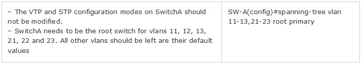
✑ The VTP and STP configuration models on Switch A should not be modified.
✑ SwitchA needs to be the root switch for vlans 11, 12, 13, 21, 22, and 23.
✑ All other vlans should be left at their default values.
Configuration Requirements for SwitchB
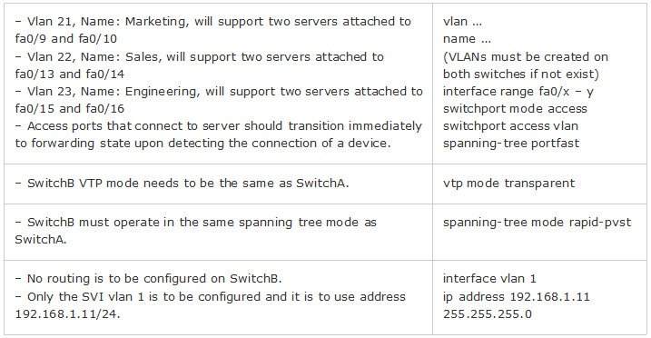
✑ Vlan21
- Name: Marketing
- will support two servers attached to fa0/9 and fa0/10
✑ Vlan22
- Name: Sales
- will support two servers attached to fa0/13 and fa0/14
✑ Vlan23
- Name: Engineering
- will support two servers attached to fa0/15 and fa0/16
✑ Access ports that connect to server should transition immediately to forwarding state upon detecting the connection of a device
✑ SwitchB VTP mode needs to be the same as SwitchA.
✑ SwitchB must operate in the same spanning tree mode as SwitchA.
✑ No routing is to be configured on SwitchB.
✑ Only the SVI Vlan 1 is to be configured and it is to use address 192.168.1.11/24.
Inter-switch Connectivity Configuration Requirements
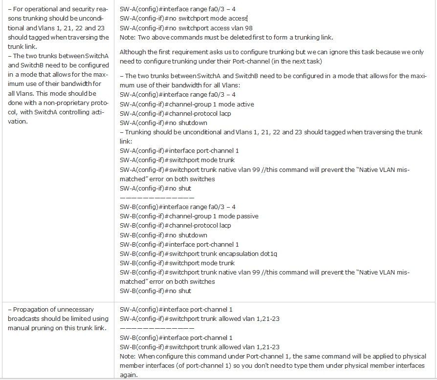
✑ For operational and security reasons trunking should be unconditional and Vlans 1, 21, 22 and23 should be tagged when traversing the trunk link.
✑ The two trunks between SwitchA and SwitchB need to be configured in a mode that allows for the maximum use of their bandwidth for all vlans. This mode should be done with a non-proprietary protocol, with SwitchA controlling activation.
✑ Propagation of unnecessary broadcasts should be limited using manual pruning on this trunk link.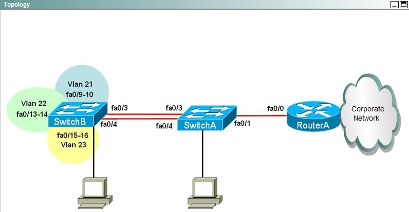


DimS
5 years, 10 months ago